Stopping
Support operations in which the train stops while crossing the weighing zone.
Dynamass · in-motion rail weighing
Measure rail-vehicle mass as trains move through the weighing zone, without a separate stop-and-weigh process. Dynamass combines retrofit rail sensors, compact trackside electronics and reporting or process integration for freight, mining and industrial applications.
Trains do not always make one uninterrupted pass. Dynamass handles stopping, rollback and reversal over the measurement zone, and supports re-weighing when a load correction needs to be checked.
The current family comprises T4i, T8i and T16i. Configuration is selected around movement patterns, track conditions, measurement performance and data needs.
System flow
Rail-mounted sensors and compact trackside electronics turn the vehicle’s movement through the weighing zone into mass information. RFID/AVI can associate results with vehicle identity, while reporting and interfaces deliver the information to the people or processes that need it.
Retrofitted rail sensors provide vehicle measurements.
Trackside electronics and software process the weighing sequence.
Integrated RFID/AVI links results to the correct vehicles where required.
Results reach operators, reports or a customer process interface.
Operational outputs
Use weighing results to review loading, identify out-of-range conditions and provide feedback to the people or systems managing the process.
Where an identified train is measured empty and later measured loaded, Dynamass can match the transactions and calculate net mass without a separate tare dataset. A configured load alert does not by itself imply automatic stopping or process control.
Retrofit measurement
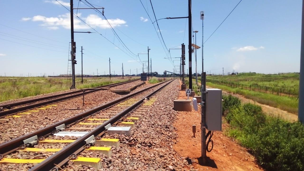
Dynamass sensing arrangements are retrofitted to the existing rail. Avoiding rail cutting and sleeper replacement reduces installation work compared with weighbridges that depend on those modifications.
As an indicative planning guide, on-site installation typically takes approximately three days for a T4i, five days for a T8i and eight days for a T16i. Actual timing depends on site readiness, track access, the configuration and commissioning requirements.
Track condition, access, power and communications still matter. We assess site requirements before confirming scope, programme and measurement performance.
Industrial train movements
Support operations in which the train stops while crossing the weighing zone.
Direction-sensitive sensors track the train’s position and recognise reverse movement.
Reverse measurements are excluded from the forward weighing sequence. RFID/AVI can help associate results with the correct vehicles when shunting changes the departing consist.
A second complete pass during the same transaction can produce a second mass measurement to check a load correction.
Rollback, reversal and re-weighing can be configured across the model family when required. They are most commonly relevant to lower-speed T4i industrial applications, but are also available for higher-speed installations with operating patterns that require them.
Model selection
Model selection considers speed, track condition, required accuracy, movement pattern and the way results will be used—not speed alone.
| Selection point | T4i | T8i | T16i |
|---|---|---|---|
| Rated operating-speed range | 0.1–20 km/h | 0.1–35 km/h | 0.1–60 km/h |
| Indicative maximum practical weighing speed† | 40 km/h | 70 km/h | 100 km/h |
| Typical accuracy per wagon* | ±0.5% | ±0.5% | ±0.5% |
| Number of weighing sensors | 4 | 8 | 16 |
| Ambient temperature | −20 to +55°C | −20 to +55°C | −20 to +55°C |
* The ±0.5% figure represents the best per-wagon performance typically achievable following site-specific dynamic calibration using pre-weighed vehicles and subject to suitable track conditions. It is not a guaranteed performance level.
† Dynamass continues to weigh above each model’s rated range, with reduced accuracy. These are indicative practical upper speeds; expected performance is confirmed for each application.
Get help selecting a model →Reporting and integration
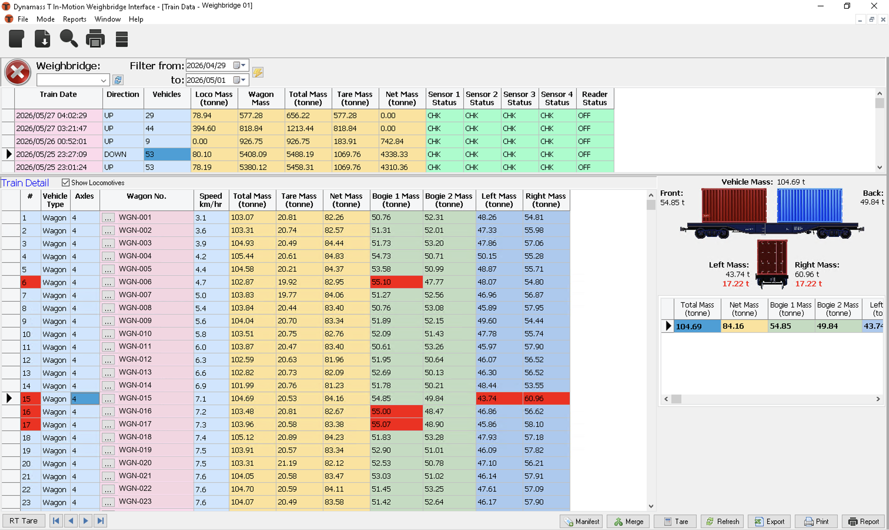
Review train and vehicle results locally, with configured load exceptions highlighted. View, print and export reports; authorised users can access configuration and diagnostics.
Vehicle results become available shortly after weighing, helping loading personnel monitor progress. The app connects through OTT’s cloud service or a custom on-site deployment.
View weighing data, prepare Loading Manifests and Release Notes, and print or export available reports through OTT’s cloud service.
Distribute results to nominated recipients using supported report formats. We confirm the formats, communications and distribution arrangement for each site.
Make vehicle results available to a customer control system for loading or unloading workflows. Interface, timing and responsibilities are agreed during application definition.
RFID/AVI links measurements to vehicle identities for transaction matching, automatic net-mass calculations and consist management.
Bad-load detection
A Bad Load Detection System (BLDS) combines weighing with a camera. When a configured undesirable load condition is detected, the system triggers an image of the wagon contents and provides an alert with the associated information.
This gives operators measurement data and a visual record to support their assessment. We discuss the load conditions, camera arrangement and alert interface needed for your application.
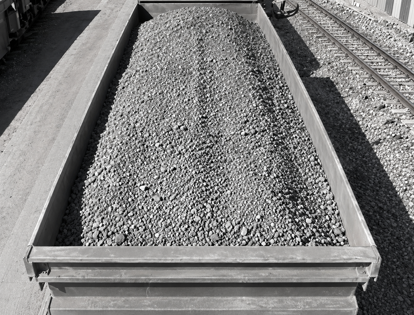
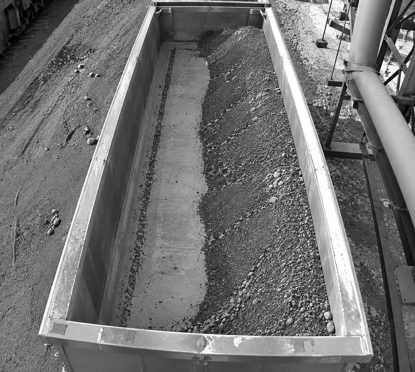
AI-generated illustrations of loading conditions. These are conceptual images, not actual camera output. Visible fill height does not establish a measured overload.
Discuss bad-load detection →Application example
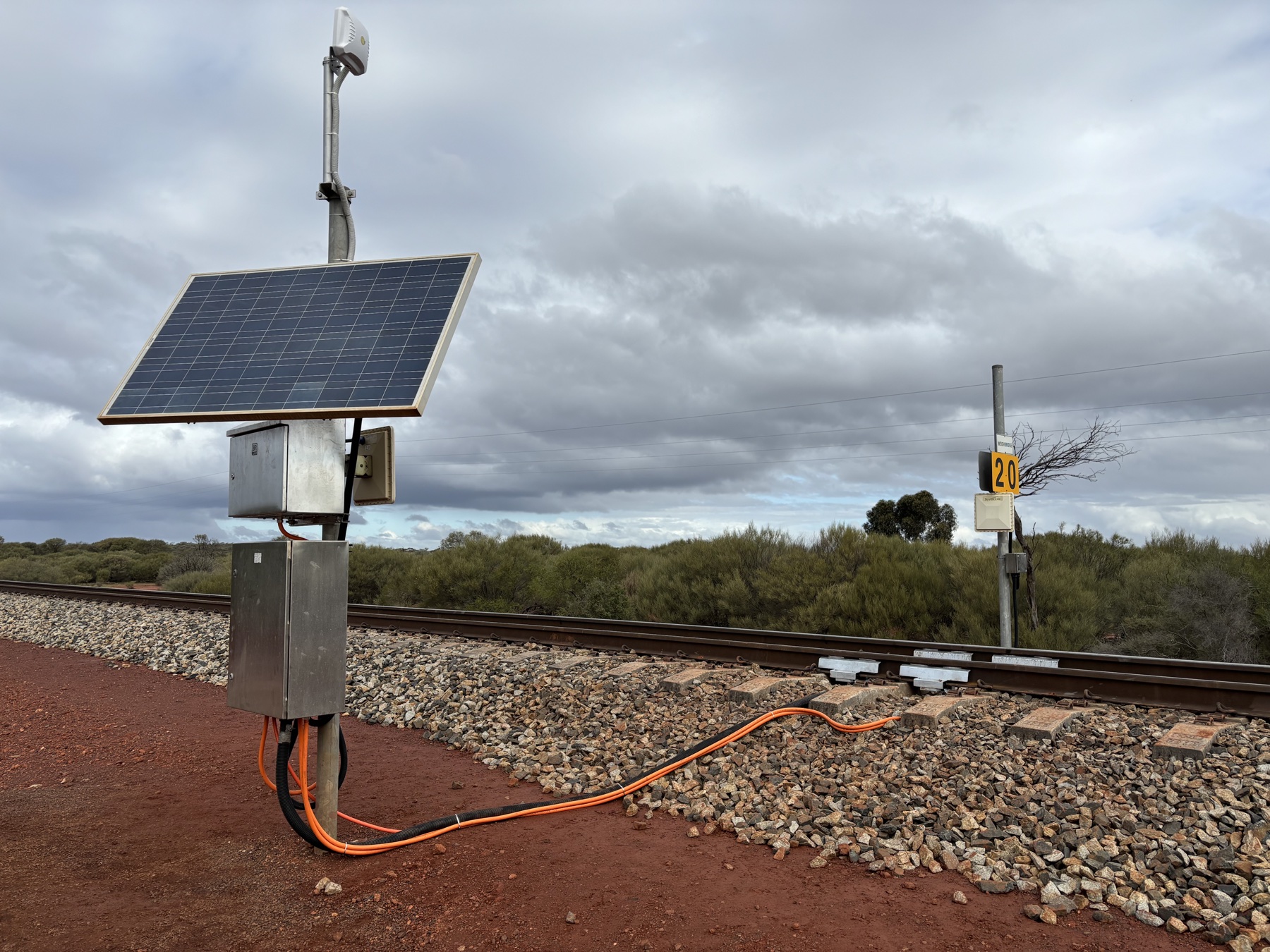
Karara Mining uses one bidirectional, solar-powered Dynamass T4i installation to verify rail-vehicle loading before product travels 220 kilometres from its remote Western Australian mine to Geraldton Port.
The original T4 operated from 2012 until July 2024. OTT installed the current-generation replacement with HMA providing local coordination, logistics and on-site assistance.
Vehicle, axle and distribution results help personnel identify conditions that need attention while they can still be corrected during the train loading operation. Remote diagnostic access and Karara’s current 24-hour support arrangement provide a defined route for issues to be captured, diagnosed and addressed.
“The weighbridge is a valuable tool and critical to the project. Any overweight wagons departing Karara are red-carded off the rail system at significant expense, so it is vitally important that loading, weight and axle loads are correct and within tolerance before departure.”
The 24-hour support arrangement described here is specific to Karara.
Installation and support
OTT supports projects from application definition through installation, commissioning and ongoing operation, working directly with customers, engineering consultancies, systems integrators and regional partners.
We consider track and train movements alongside power, communications, identification and the destination of the data. Remote configuration and diagnostics depend on the configuration and the site’s agreed connectivity and access arrangements.
Support or upgrade an existing system →Application review
Tell us where the system will operate, how trains move through the site and what you need the weighing results to do. Include the expected speed range, stoppages or reversals, load corrections, identification and reporting or process requirements.